
Schematics and layout
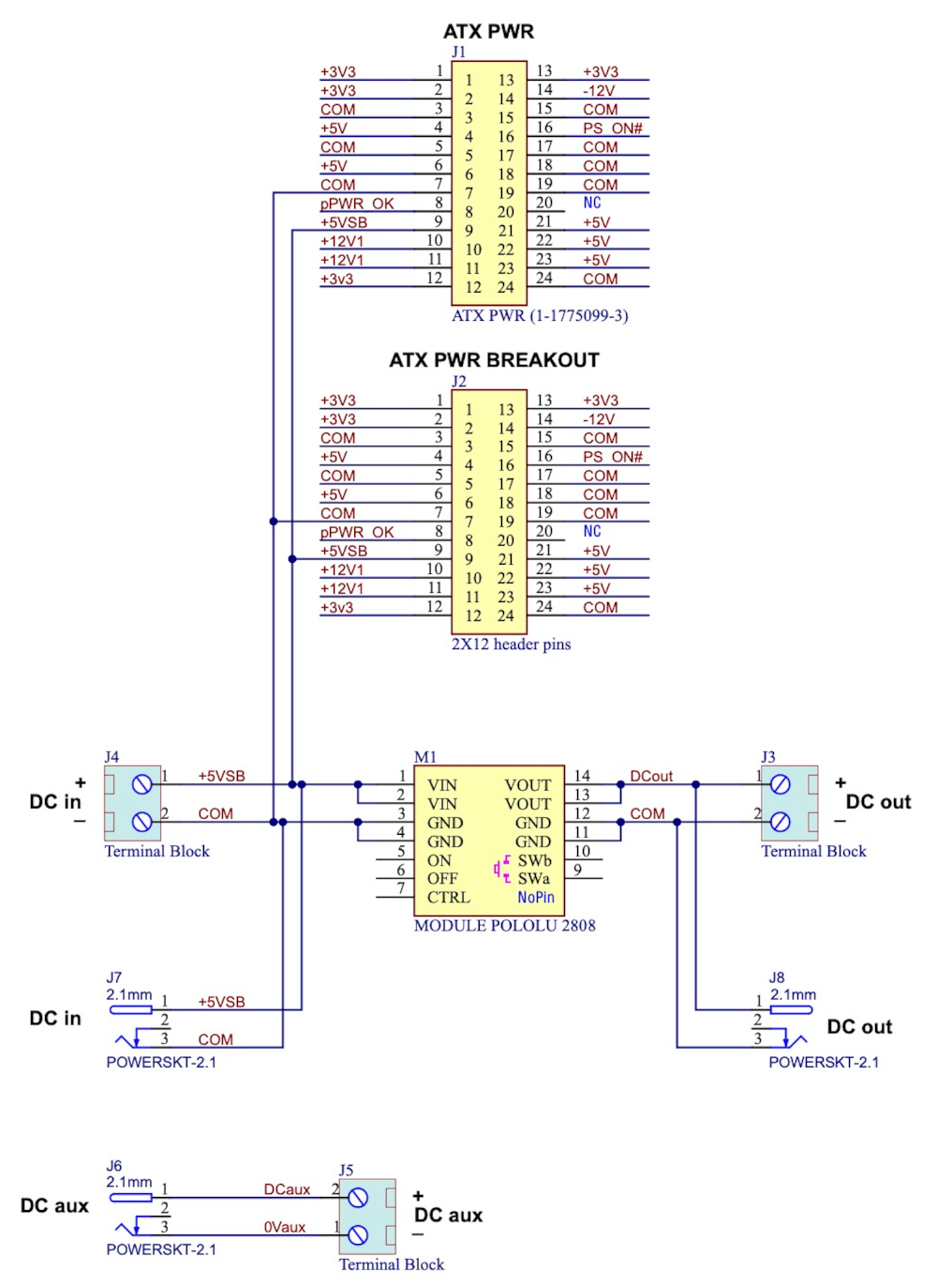
ATLANTIS for MiSTer schematics
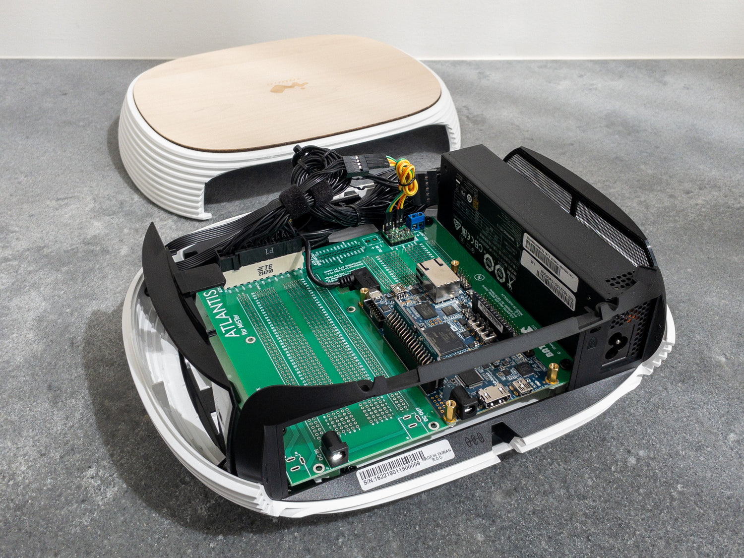
ATLANTIS for MiSTer is intended to simplify powering your MiSTer FPGA by utilising the PC case power button, for power on/off.
Some simple options include;
Powering from an external DC plug
1) Soldering a DC jack to J7, Pololu 2808 module to M1 and a terminal block to J3; outputting power via a DC power pigtail into your MiSTer whenever the PC case triggers the 2808 switch.
Powering from an internal ATX PSU 5V standby source
2) Soldering an ATX connector to J1, Pololu 2808 module to M1 and a terminal block to J3; outputting power via a DC power pigtail into your MiSTer whenever the PC case triggers the 2808 switch.
(The ATX +5Vsb is connected by default to the Pololu Vin and many modern ATX power supplies will carry 3-4A on this line; sufficient to power most MiSTer setups)
For either option described here; a DC pigtail output from J3 could be connected to MiSTer by a DC plug or directly soldered to the MiSTer power input socket.
Primary side views
-
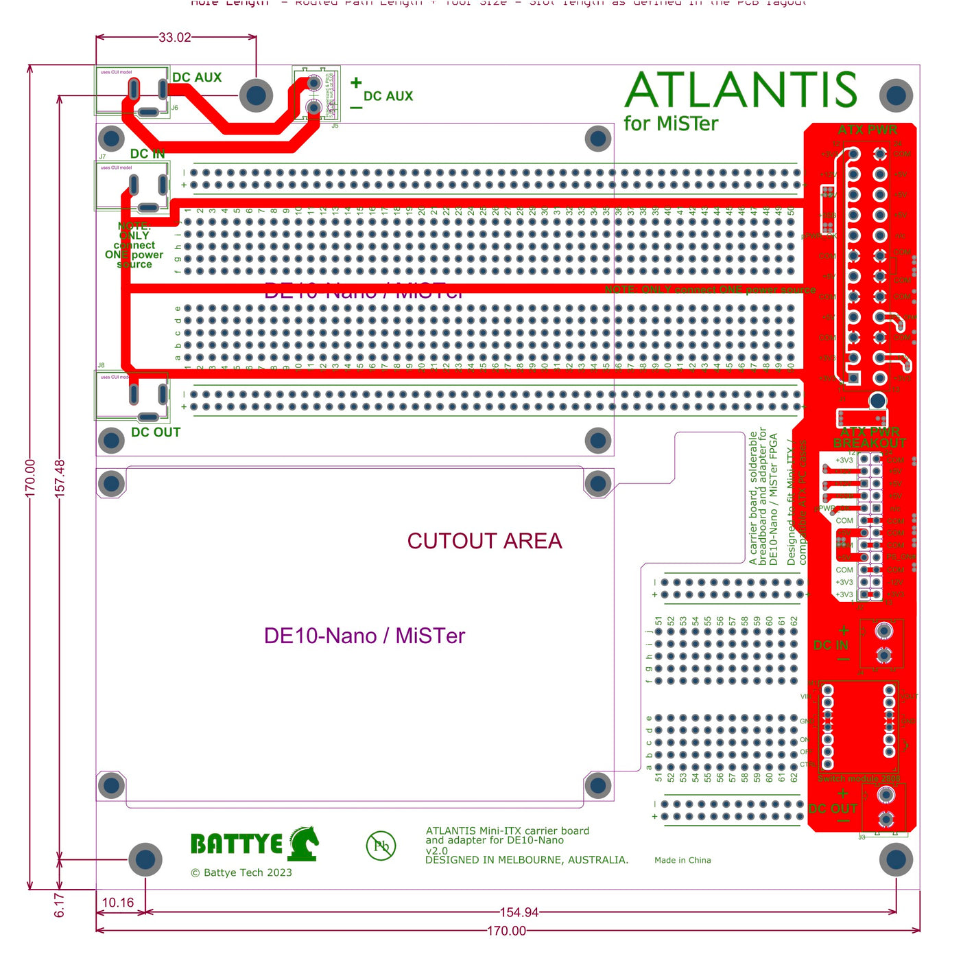
Red pattern
Primary side assembly demonstrating top copper pattern.
-
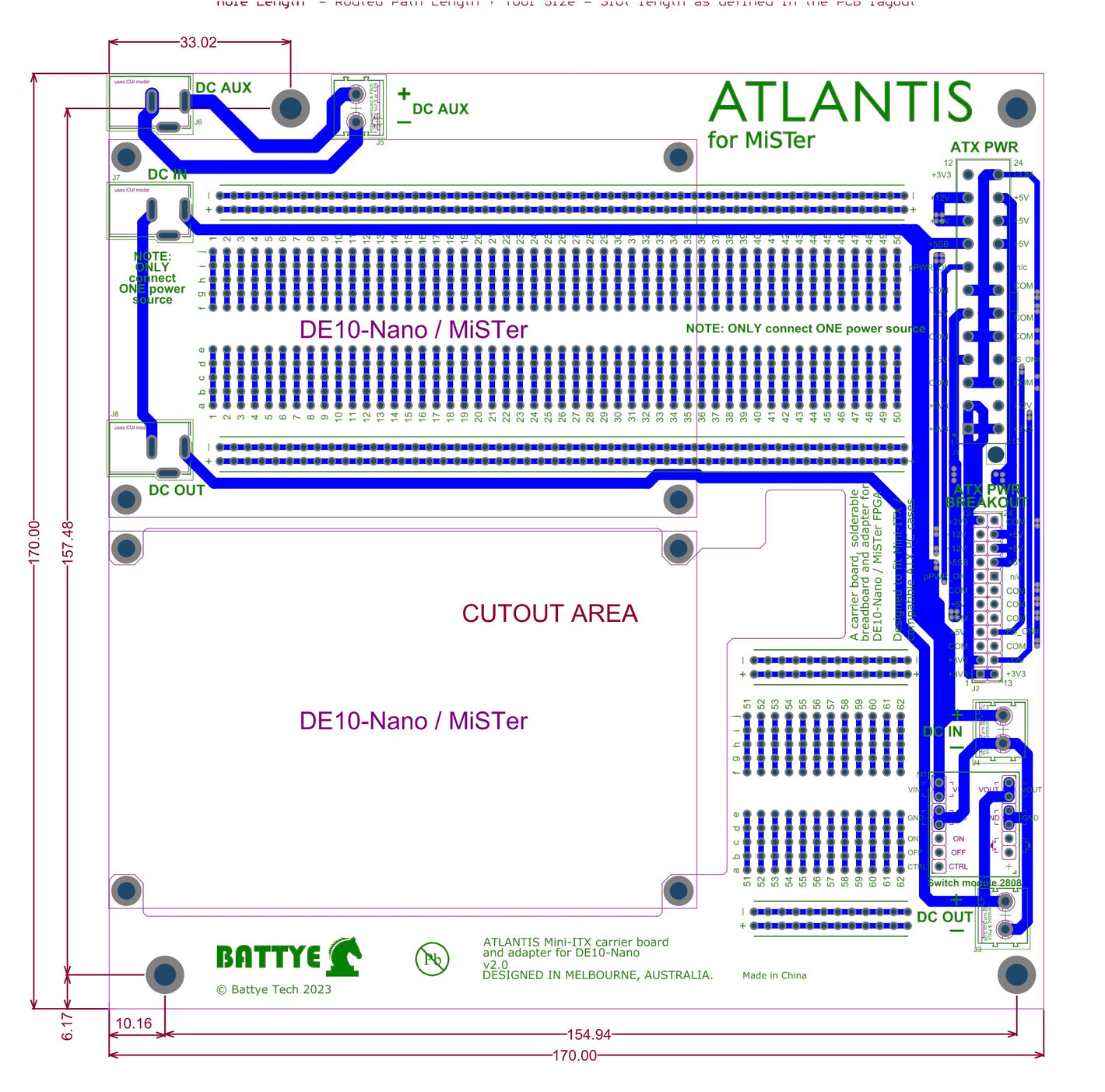
Blue pattern
Primary side assembly demonstrating secondary (bottom) copper pattern.
-
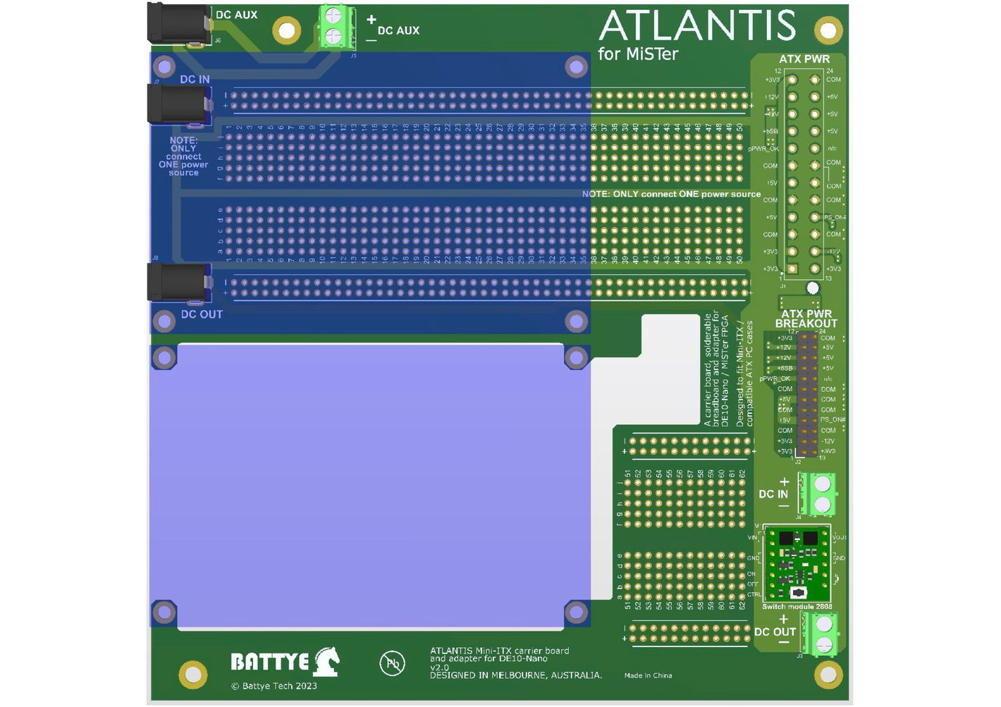
3D model of a partly populated board
There are two locations available for a DE10-Nano or DE10-Nano sized board (transparent blue areas). Risers may be used to elevate a secondary board above any DC jacks if required.


Compatible parts
ATX connector (eg TE Connectivity AMP Connectors 1-1775099-3)
DC jack (eg Cliff electronics DC10A 224959)
2pin terminal block 5mm (eg Jaycar HM3172)
Pololu mini pushbutton module 2808 LV
Working with the Pololu mini pushbutton module 2808
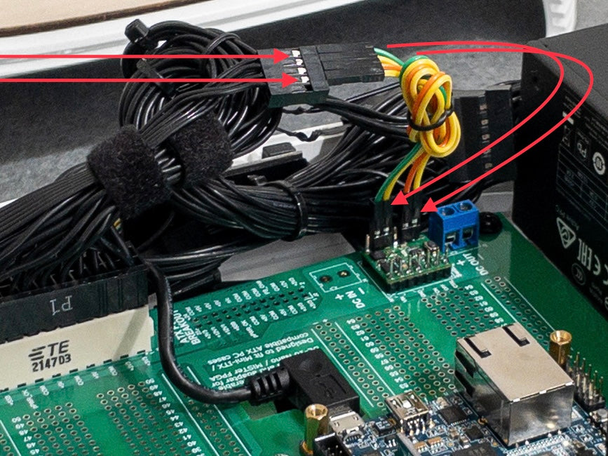
The Pololu 2808 LV module allows you to easily utilise the PC case switch and LEDs. The package includes pin headers that can connect to the PC case SW and LED connectors. In some PC cases these will be individual single or double female connectors, or, as in the example of this InWin case, male to female jumper wires can be used to interface with the 9pin connector.
As shown in the schematic at the top of this page, DC power input to the Pololu Module is incorporated into the ATLANTIS via DC jack input or the ATX +5Vsb. If an alternate power source is desired, a terminal block at J4 is also directly connected to the Vin of the 2808 module.